ラズパイのCPUを100%稼働してみた
◯やりたいこと
ラズパイのzero(1コア)と3B(4コア)のCPUを100%稼働させてその温度変化を確認する。

◯やったこと
・CPUを100%動作にする方法
CPUの100%稼動状態を作り出す方法は単純にpythonの無限ループで行います。SSHを利用してターミナルソフトでログインし、pythonのコマンドプロンプトを開いて
while True: pass
と実行すれば無限ループに入りCPU使用率が100%に上昇します。

htopで確認すると100%になっているのが確認できます。

4コアの3Bの場合も同様の手順を踏めばよく、別々に起動したターミナルソフトで4回実施すれば4コアとも100%稼働になります。

・温度の上昇状況
zero
zeroは両サイドを鉄板で挟んで放熱させるパッシブ型ケースに格納。
この状態で100%稼働した時の温度の上昇具合は

こんな感じ。
温度上昇の山が2つあるのは深夜帯にラズパイが再起動し通常運転に戻ってしまったためで、朝から再びフル稼働させています。温度は41℃から50℃へ瞬間的に跳ね上がっていますがそれ以外のデータにあまり変化がない点が気になります。
ただ、過去2週間分の推移記録を見てみると

こちらも温度以外の値の変化がほとんどないので、もしかしたらzeroは細かな周波数制御は行っていないのかもしれません。ためしにもう少し熱くしてみようと100%稼働してアチアチになっている3Bに載せてみたところ

更に8℃上がって58℃。しかしやっぱり他の数値には変化ありません。zeroは一旦走るとそのまま走りっぱなし、という仕様なんでしょうか。(いろいろと設定はできるようなんですが…)
3B
3BもCPUの熱をケースに伝えケースで自然冷却するパッシブタイプ。

こちらは100%稼働させると何と一気に25℃も上がる大爆熱モード。

55℃の平常運転から80℃へ急激に上がって放熱が追いついていないのがわかります。動作周波数にも変化があり、平常時600MHz〜1.4GHzで上下していたものが1.2GHz固定になっています。いわゆるサーマルスロットリングというやつでしょうか。
・卓上扇風機による強制空冷
実験とはいえ80℃で常時走らせるのは精神衛生上あまりよくありません。そこでさっそく電池式の卓上扇風機をラズパイの前に置き強制空冷による冷却実験を行っていきます。

風量は2段階に調整できるので強弱モードの違いも見てみます。
zero
さすが強制空冷、効果は絶大です。弱モードでも15℃も下がっています。

ラズパイがくしゃみをしているのが聞こえます。
ただまだノーマル稼働時の温度には戻れていませんので風量を強モードにしてさらに送風。

しかし意に反し温度は大して変化なし。ありゃ。
と言うことはこの辺が冷却温度の限界点なんでしょうか。
3B
空冷の効果は4コア3Bの方が大きく出ました。CPU温度は20℃もの急降下です。

冷えすぎて風邪をひかないか心配になるレベルですね。ただまだサーマルスロットリングの解除に至っていませんので風量を強モードへ。しかしzeroと同様あまり温度が下がりませんでした。
60℃付近ではちょっとだけ周波数コントロールが復活しています。どうやらこのあたりに周波数制御のトリガー基準があるようです。
・室温を下げる
この実験をしている場所は階段下の物置。室温は今年の異常猛暑に引っ張られ常時30℃以上あります。そこでクーラーを持ち込んで室温を25℃まで下げてみることにしました。(実際は27℃までしか下がりませんでしたが…)
zero
zeroは室温の影響がすぐに現れました。

どうやら冷却できる範囲にまだ余裕があるようです。

ラズパイのCPU状態の推移をグラフにすると…
◯やりたいこと
ラズパイのCPU動作状態推移(温度、クロック数、電圧、メモリ)をグラフにして動作状況を把握する。
◯やったこと
ワガ家の「えだまめ」ネットワーク、ラズパイサーバー達は基本パッシブ型の空冷ケースで運用しており冷却は自然対流にお任せとなってます。初期の頃こそファン付きのアクティブタイプで空冷していたのですが、やたらとホコリは呼ぶし、いわゆる安普請ファンなのでしばらくすると軸なりを始めかなりにぎやかに。挙げ句の果てにブーンといって回らなくなってしまう、というパターンを繰り返したのでいい加減あきれてファン付きは全て撤去してしまいました。
ラズパイ達はラズパイ用アプリなどでたまに温度を測ったりしてある程度の動作状況を把握していたのですが、ここで改めて定期的に情報を集めグラフにして動作状況を見てみることにしました。
・グラフ
SQLサーバー (4B+)

「えだまめ」ネットワークの記憶中枢、SQLサーバーの1週間分の動作状況です。記録は概ね1分おきに取得しています。動作温度はほぼ50℃前後で一定、ケースはけっこうアツアツです。ただSQL的な重労働をかけてもそれ程温度は上がらないのでまあ許容範囲内かなと思ってます。動作クロックは1.5GHz〜600MHzの範囲で少々驚く頻度で上下しており、mariaDBは意外とエコなソフトなのかもと再認識していました。
ちなみにSQLサーバーはSSDで運用できるパッシブ型のケースに入れて動作中。

さらにSSDを外部にもう一つ接続してあり、

・階段下物置のサーバー達 (4B+,3B+,3B)
・Julius サーバー

日本語解析用サーバーの動作状況。温度は52℃前後を行ったり来たり。1週間分のグラフだと詳しくわからないのですが、拡大してみるとテレビの音声や人の会話が多い時間帯は稼働率が上がり温度が上昇する傾向があります。動作クロックは3B
ですので1.4GHz〜600MHzの範囲。このソフトも結構こまめに動作周波数が変化しています。
途中グラフが凹引っ込みしている部分は電池式の卓上扇風機を前に置いてみた時。効果はテキメンで10℃以上温度が下がっており強制空冷の威力が垣間見えます。
・グラフサーバー

グラフ描画用としてGUIを動作させ matplotlibで画面描画、画面ファイル出力を担当させているサーバーのグラフです。webサーバーに使用するグラフなどを要求により定期的に出力しています。GUIを動作させているせいかCPUクロックは上限に張り付いていて、マシンへの描画要求が重なるとCPU温度がポンと上昇しています。
・スケジュールサーバー

scheduleモジュールを利用し、定時、定刻、定サイクルに指定コマンドをサーバー達に送信するサーバーのグラフです。毎年の家族の誕生日にハッピーバースデーを演奏、毎日7時・お昼・19時にNHK時報、1分サイクルでCPUデータを集めるなど結構忙しく動いているサーバーです。夜にはSQLが各サーバーからSFTPでデータを吸い上げバックアップするコマンド送信も担当していて、サーバーの中では一番活躍度の高いサーバーです。そのせいか動作クロックも上限に張り付き気味です。
・温度でソフトのバグを発見
・Django(Web)サーバー

Djangoを走らせているWebサーバーです。外部には公開していません。グラフは10時間分の記録ですが、このサーバー、なぜか他のサーバーに比べて温度が60℃と異常に高く動作していました。どうもおかしいと思ってhtopでCPUの動作を見てみたところ4コア中1コアが100%で稼働中。これでは高温もあたりまえです。
どれどれと原因原因を追求したところ、LED点滅の時間待ちを時刻変化のチェックだけで済ませたためにおきた高速ループのバグ。sleepを挟まなくてはならないやつです。マルチプロセスを使う時によくやってしまいます。
グラフはこのバグをFixした後の温度の変化。現金なものでFix後8℃も温度が下がっています。ソフトの書き方一つでCPU温度に影響が出るという事を身を持って経験です。
WROOM-02のIO16とリセット端子をチップ抵抗でつないでみる
◯やりたいこと
WROOM-02シンプル版ボードでディープスリープを利用するためのIO16端子-リセット端子接続を、普通のカーボン抵抗でなくチップ抵抗でつないでみる。
◯やったこと
コンパクト版のブレークアウトボード、

小さくてかなり便利なのですが、外部にIO16端子が出ておらずリセットと接続ができないのでデープスリープが使えないという致命的欠陥がありました。シンプル版と同じピン出力を持つESP-01も同じ問題をかかえていたのですが、世の中にはこれをクリアするアイデアを出している人達が結構いて、かく言う私もそのアイディアを拝借しESP-01でのディープスリーブ実験を行ってきました。

ものが変わりESP8266からWROOM-02になっても理屈は同じ、シンプル版でもブレークアウトボード上で直接抵抗でつないで運用していましたが

ふと「チップ抵抗でつないだらもっと見栄えがよくなるんじゃないだろうか。」
そこでWROOM-02のピン間隔を調べてちょうど合うサイズのチップ抵抗を準備。

2012サイズ1kΩ抵抗。これをカーボン抵抗の代わりにつけてみたところ

おぉ、ピッタリ。でっぱりがなくなり見た目もスッキリです。
これはいい感じ。
ちなみに取付けに際しては、抵抗ウラにある端子のハンダを吸い取り線でへこまし気味に吸い取っておくのがコツです。
◯やってみて
カーボン抵抗取り付けは結構面倒な作業だったため何となく気が進まずになかなかディープスリープ可能なシンプル版の増産ができなかったのですが、チップ抵抗にしたら超簡単、すぐ作ることができるようになりました。
おかげ様でチップ抵抗版の温度計ロガーを大増産できています。

(↑とは言ってもまだ2個しか作ってませんけど…)
BME280・BH1750で測定した2年半分のデータを見てみると…
◯やりたいこと
BME280 とBH1750で収集した温湿度・気圧・照度のデータが2年半分たまっていたので実際にグラフに表示してみる。
◯やったこと
・データのグラフ化
初期はラズパイ・後半はESP8266のもと、BME280(温湿度・気圧センサー)・BH1750(照度センサー)で測定してきた居間のデータをラズパイの matplotlibでグラフにしてみました。

測定数は1要素で10万を超えており、4要素表示となるとラズパイにとってもかなりの重労働の様。作図に結構時間がかかります。途中電池切れでロストしている部分もありますが、まあ全体的な流れはつかめるのでよしとしときます。
・考察
(1) 温度
部屋は寒ければ暖房、暑ければ冷房をつけるので温度はそれほど大きい変化がなく記録されています。寒がりなので20℃より下がれば即暖房、暑がりなので28℃を越えれば即冷房、なもんで概ね20℃〜28℃位の範囲に収まっています。
ただ特徴的なのは去年の暮れから今年初めの冬期間の温度。例のウクライナ関連で電気料が2〜3割上昇しオール電化の我が家には途端にピンチが襲来。そのため少々寒いくらいでは暖房を入れず人型寝袋を着て寒さをしのぎました。その結果としてグラフが18℃あたりに集まってきています。どうやら室温はその時の社会情勢を示す傾向があるようです。
・(2) 湿度
冬は乾燥、夏は湿気、当たり前のことですがグラフにすると露骨に季節感が出ますね。25%〜80%と広範囲。大体50%を超えると夏、切ると秋てな感じでしょうか。
・(3) 気圧
気圧はもうガチャガチャ。全体的な傾向はないように見えるのですがあえて特徴を見出すとすれば低気圧の数でしょうか。990HPaを下回る低気圧の数を数えればその年の天候不順状態がわかる?もう少し長い期間で見てみれば地球温暖化の状況がわかるかもしれません。夏は気圧の変化が比較的小さいのも発見です。
・(4) 照度
照度センサーは部屋の北側の壁に下げており窓からの直射日光が当たらないため部屋全体の空間照度?を計っています。照度は季節感とは反対に夏暗く、冬明るくなります。これでわかるのは太陽の高度。太陽の高度が高い夏は日差しが室内の奥まで入ってこないので全体的に暗くなり、高度が低い冬は日が奥まで入り部屋が明るくなります。実は古い建屋に多い長い庇はこれを応用した自動ブラインド設備。夏の日差しをさえぎり冬の陽射しだけを取り入れるアイディアグッヅです。最近の建物は窓の庇がすっかりなくなってきているのでひょっとしたら結構無駄な空調費がかかっているのかもしれません。
◯やってみて
居間の2年半分の温湿度・気圧・照度データをグラフに表したところ
温度: 社会情勢
湿度: 季節
気圧: 地球温暖化状況
照度: 太陽高度
を表すことがわかりました。何かの参考にどうぞ。
(↑半分冗談です。本気にしないでくださいね。)
BME680で温湿度・気圧計の作成(6) 簡易版の製作
◯やりたいこと
(4)、(5)で作った温湿度計が電池の完全放電実験に入っているため、その他の実験用に電池ボックス一体型の簡易温湿度計ロガーを作成する。

◯やったこと
・作成したブレッドボード版の温湿度計は…
(4)、(5)でブレッドボード上に作った温湿度計は現在単4乾電池でどれくらい動作するか実験中です。

完全放電を狙っているのでさすがにエネループはまずいだろうとアルカリ電池を利用中。計算上2週間ほど動く予定ですが

現在11日目で電池電圧2.7V。極めて順調に稼働しています。
ただ放電中はスケッチのバージョンアップ等の実験ができなくなり少々時間がもったいないモード。そこで別に簡易型を作りそちらでいろいろ実施していく事にしました。
・部品の準備
(4)で準備した
・wroom-02(ESP8266) ブレークボード:シンプル版
・BME680
・MCP1640 DCDCコンバータモジュール
に加え
・単3 3本用電池BOX
・電池サイズユニバーサルボード
・抵抗、コンデンサ
・ピンソケット
を準備します。

・製作
使用するボードがスルーホール仕様ですので、製作に入る前にDCDCモジュールの絶縁を行なっておきます。
裏面に

カプトンテープを貼って

カット。

モジュールを分割する際にできたデコボコはピンソケットと干渉するためヤスリで平らにしておきます。

全体的な部品の配置はこんな感じ。

DCDCモジュールを中心に各部品を取り付けていきます。


裏面はこんな感じ。

配線終了後はいつも通りアルコールと歯ブラシでゴシゴシキレイにして


電池動作用にスナップをつければ簡易版のボードが完成。

小一時間ほどの作業で完成です。
・動作確認
さっそく電池をセットし電圧を調整しながら配線チェックを行います。

その後LチカでWroom-02の動作確認をし

最後にBME680 をセットして(5)で作成したスケッチを書込むと簡易型温湿度計が完成。
1分単位で記録させるとキチンとデータを送ってきているので無事動作している様です。

◯やってみて
一度動作確認をしているので稼働まで特に問題が発生せず、製作作業が楽で助かりました。
今後このマシンでは主にスケッチ面での改善、
・省電力化の追求
・既存温度計との比較
・Gas測定値の設定・応用方法の勉強
ブレッドボードのマシンではハード面での改善、
・起動に失敗しないCE用コンデンサの最適解
・手動起動をリセットでなくCEへの変更検討(現状はリセットシーケンスに違反している)
などを行っていく予定です。
◯その後の実験結果
・省電力化
BME680ライブラリを見てたところ、begin関数の第2引数をfalse(デフォルトはtrue)で呼ぶとガスヒーターオフの状態で起動できるとの事。それではと、省電力化の手始めにガスヒーターなしの立ち上げを行って見る事にしました。結果は以下の通り。

ヒーターオン時に出ていた電流の山が消えてなだらかになっています。手動起動でない場合はOLEDの表示待ち時間をパスする様にした事もあり稼働時間は一気に4秒台に。

3回分の立ち上げ平均をとってみても4秒台。


これだと電池の持ちが2倍になる勘定です。一気に省電力化が進む事に。シメシメ。まあ、もちろん皮算用なんですが…。
・既存温度計との比較
居間で測定中(BME280)の温度計と今回作成した温度計の測定差を1日(144回)の平均で比較してみました。

最初の4日間が Gas測定オフモード、後半の4日間がオンモードの時の結果です。オフモードの段階でBME680 の方が 0.8℃、湿度で 4%程度高く記録されていました。まあ誤差の範囲内でしょうか。気圧にはほとんど差がありませんでした。
ただヒーターをオンにすると0.5℃ほど測定温度が上がります。Gas測定時は0.5℃の温度補正をした方がいいようです。
BME680で温湿度・気圧計の作成(5) スケッチの作成
◯やりたいこと
(4)で確定した回路図をもとにスケッチを作成する。

(現在は実際に電池稼働での実験に入っています。)
◯やったこと
・スケッチの作成
現時点で動いているスケッチは以下の通りとなっています。
/**
*
*    WiFi 温湿度・気圧計 WR02_BME680_OLED v0.0.5b
*
*      CPU    : WROOM-02(ESP8266) シンプル版
*      Pin Function
*        IO0  : SCL
*        IO1  : TX (OLED Power)
*        IO2  : SDA
*        IO3  : RX (SW)
*        IO4  : -
*        IO5  : -
*        IO12 : -
*        IO13 : -
*        IO14 : -
*        IO15 : -
*        IO16 : Reset出力(OnBord)
*        TOUT : -
*      Board
*        ESP8266 Community : Generic ESP8266 Module
*        URL : http://arduino.esp8266.com/stable/package_esp8266com_index.json
*
*/
// Standerd Library	(IDE v1.8.19)
#include              <Arduino.h>
#include              <time.h>
#include              <Wire.h>

// Board Library (ESP8266 Boards v2.7.2)
#include              <ESP8266WiFi.h>
#include              <WiFiClient.h>

// Install Library
#include              <Adafruit_GFX.h>     // v1.11.3
#include              <Adafruit_SSD1306.h> // v2.5.7
#include              <Adafruit_Sensor.h>
#include              <Adafruit_BME680.h>  // v2.0.2

// Global Value
/* WiFi */
#define CONN_SSID     "YOUR_SSID"
#define CONN_PASS     "YOUR_PASSWORD"

/* My ID,IP,MAC */
String  MY_NAME =     "ESP093";

IPAddress ip          (YOUR_IP);
IPAddress gateway     (YOUR_GATEWAY);
IPAddress dnServer    (YOUR_DNSSERVER);
IPAddress netmask     (YOUR_NETMASK);

/* UART */
#define TX            1         // D1
#define RX            3         // D3

/* I2C */
#define I2C_SDA       2         // D2
#define I2C_SCK       0         // D0
#define I2C_CLK       50000     // fSCL=50KHz

/* WakeUp Interval */
#define wup_itvl      10        // [分]

/* SW */
#define SW_RES        RX
#define SW_on         HIGH

/* OLED */
#define OLED_ADR      0x3C      // I2C ADDRESS
#define OLED_RESET    -1        // Reset pin # (or -1 if sharing Arduino reset pin)
#define SCREEN_WIDTH  128       // OLED display width, in pixels
#define SCREEN_HEIGHT 64        // OLED display height,in pixels
#define OLED_PWR      TX        // OLED 電源制御ピン
#define OLED_off      LOW
#define OLED_on       HIGH

Adafruit_SSD1306      display(SCREEN_WIDTH, SCREEN_HEIGHT, &Wire, OLED_RESET);

/* NTP DATA */
#define JST           (3600 * 9)
#define DAYLIGHTOFFSET_JST (0)
#define NTP_SERVER1   "ntp.nict.jp"         // NTP1
#define NTP_SERVER2   "ntp.jst.mfeed.ad.jp" // NTP2
static const char *pszWDay[]  = {"Sun", "Mon", "Tue", "Wed", "Thu", "Fri", "Sat"};
static const char *pszMonth[] = {"Jan", "Feb", "Mar", "Apr", "May", "Jun", "Jul", "Aug", "Sep", "Oct", "Nov", "Dec"};

/* BME680 */
#define SEALEVELPRESSURE_HPA (1013.25)
#define BME_ADR       0x76
Adafruit_BME680       bme;      // I2C接続:引数なし

/* Flag */
boolean flg_wifi =    false;    // True: WiFi on
boolean flg_boot =    false;    // True: Manual boot

/* Value */
float   tmp, hum, prs, gas;

///// ハードウエア 初期設定
void setup() {
  /* Serial (TXピンをGPIOとして利用) */
 Serial.begin(115200,SERIAL_8N1,SERIAL_RX_ONLY);

  /* Manual boot Check */
  pinMode(SW_RES, INPUT);
  if(digitalRead(SW_RES)==SW_on) flg_boot = true;

  /* Sleep Mode */
  wifi_set_sleep_type(MODEM_SLEEP_T);

  /* I2C */
  Wire.begin(I2C_SDA, I2C_SCK); // I2C pins
  Wire.setClock(I2C_CLK);       // I2C clock(fSCL)
  delay(100);

  /* OLED */
  digitalWrite(OLED_PWR, OLED_off);
  pinMode(OLED_PWR, OUTPUT);
  dsp_start();

  /* WiFi */
  WiFi.config(ip, gateway, netmask, gateway);
  if (!wifi_connect()) wifi_end();
  flg_wifi = true;

  /* NPT */
  configTzTime("JST-9", NTP_SERVER1, NTP_SERVER2);
  if (!ntp_connect()) wifi_end();

  /* BME680 */
  unsigned long timeout = millis();
  while(millis() - timeout < 1000) {
    if (bme.begin(BME_ADR)) {
      delay(150);
      break;
    }
    delay(150);
  }
  if (!bme.begin(BME_ADR)) wifi_end();
}

///// メインルーチン
void loop() {
  // 時刻表示
  dsp_datetime();

  // 温湿度・気圧測定(BME680)
  unsigned long timeout = millis();
  while(millis() - timeout < 1000) {
    if (bme.performReading()) {
      tmp = bme.temperature;
      hum = bme.humidity;
      prs = bme.pressure / 100.0;
      gas = bme.gas_resistance / 1000.0;
      break;
    }
    else delay(250);
  }

  // DATA 表示
  dsp_data();

  // SQL DATA送信
  /* ~ ここにWiFiでデータを送信するスケッチを書く 〜 */

  // 測定結果表示
  wifi_stop();
  if (flg_boot) delay(8000);

  // 計測終了
  wifi_end();
}

///// Display Control /////
/* OLED 起動処理 */
void dsp_start() {
  // Manual Boot Check
  if (!flg_boot) return;

  // OLED
  digitalWrite(OLED_PWR, OLED_on);
  delay(500);

  // 初期化
  display.begin(SSD1306_SWITCHCAPVCC, OLED_ADR);

  // 初期表示
  display.clearDisplay();
  display.setTextColor(WHITE);
  display.setTextSize(1);
  display.setCursor( 10, 20);
  display.print("Sensor Startup..");
  display.display();
  display.clearDisplay();
}

/* OLED 時刻表示 */
void dsp_datetime() {
  // Manual Boot Check
  if (!flg_boot) return;

  // NPT 現在時刻の取得
  time_t timeNow   = time(NULL);
  struct tm* tmNow = localtime(&timeNow);

  // DATE 文字列作成
  char fmtDate[11];
  sprintf( fmtDate, "%02d/%02d(%s)",
           tmNow->tm_mon + 1,
           tmNow->tm_mday,
           pszWDay[tmNow->tm_wday] );
  // TIME 文字列作成
  char fmtTime[6];
  sprintf( fmtTime, "%02d:%02d",
           tmNow->tm_hour,
           tmNow->tm_min );
  // 表示
  display.clearDisplay();
  //display.fillRect(  0,  0,128, 16,BLACK);
  display.setTextSize(1);
  display.setCursor(  4, 4);
  display.println(fmtDate);
  display.setTextSize(2);
  display.setCursor( 68, 0);
  display.println(fmtTime);
  display.display();
}

/* OLED 測定結果表示 */
void dsp_data() {
  // Manual Boot Check
  if (!flg_boot) return;

   // 変数初期化
  char buf1[9], buf2[21];

  // 測定結果表示
  display.setTextColor(WHITE);
  display.setTextSize(1);
  /* Temp 表示 */
  display.setCursor(  0, 19);
  dtostrf          (tmp,4,1,buf1);
  sprintf          (buf2, "Tmp: %sC", buf1);
  display.print    (buf2);
  /* Humi 表示 */
  display.setCursor(  0, 28);
  dtostrf          (hum,4,1,buf1);
  sprintf          (buf2, "Hum: %s", buf1);
  display.print    (buf2);
  display.print    ('%');
  /* Press 表示 */
  display.setCursor(  0, 37);
  dtostrf          (prs,4,0,buf1);
  sprintf          (buf2, "Prs: %sHp", buf1);
  display.print    (buf2);
  /* GAS 表示 */
  display.setCursor(  0, 46);
  dtostrf          (gas,4,1,buf1);
  sprintf          (buf2, "Gas: %s", buf1);
  display.print    (buf2);

  /* MY_NAME 表示 */
  display.setCursor( 70, 54);
  display.print    ("   "+ MY_NAME);

  display.display();
}

/* OLED 終了処理 */
void dsp_end() {
  // Manual Boot Check
  digitalWrite(OLED_PWR, OLED_off);
}

///// WiFi Control /////
/* WiFi接続開始処理 -> True:WiFi接続完了, False:WiFi接続失敗 */
boolean wifi_connect() {
  // WiFi 接続サイクルスタート(接続->確認->再接続) 3トライ
  for(int i = 0; (i < 2); i++) {
    // WiFi接続 接続が記憶されていない場合接続情報を記憶させ次回自動接続にする。
    if (WiFi.SSID() != CONN_SSID) {
      WiFi.persistent(true);
      WiFi.mode(WIFI_STA);
      WiFi.setAutoConnect(true);
      WiFi.begin(CONN_SSID, CONN_PASS);
    }

    // 5秒間 0.5秒毎に接続確認
    unsigned long timeout = millis();
    while(millis() - timeout < 10000) {
      // 接続できた場合 Trueリターン
      if(WiFi.status() == WL_CONNECTED) return true;
      // 未接続は 500ms待ちしてループ
      delay(500);
    }
  }
  // WiFi 接続不可 エラーリターン
  return false;
}

/* WiFi stop処理 */
void wifi_stop() {
  if (WiFi.status() == WL_CONNECTED) {
    WiFi.persistent(false);
    WiFi.disconnect(); // ステーションモード維持,ssid・passwordをクリアしない
    delay(10);
  }
}

/* WiFi stop,終了処理 */
void wifi_end() {
  // 現在時刻取得
  time_t tmUnix    = time(NULL);           // unix
  struct tm* tmNow = localtime(&tmUnix);   // unix

  // WiFi切断
  wifi_stop();

  // 現在から起動までの分を計算
  int minSlp =
    (wup_itvl<2) ? 1:(wup_itvl-(tmNow->tm_min % wup_itvl));

  // 30秒過ぎは起動を30秒早める
  int secSlp = 0;
  if (tmNow->tm_sec>30) {
    minSlp = minSlp-1;
    secSlp = 30;
  }

  // 諸機能停止
  dsp_end();

  ESP.deepSleep((minSlp*62+ secSlp)*1000*1000);
  delay(500);
}

///// NTP Control /////
/* NTP 同期処理 */
boolean ntp_connect() {
  // NTP サーバー同期確認 (max 5sec)
  unsigned long timeout = millis();
  while (millis() - timeout < 10000) {
    // 現在時刻読込
    time_t timeNow   = time(NULL);
    struct tm* tmNow = localtime(&timeNow);

    // NPT同期完了 & 起動時間は正常リターン
    if(tmNow->tm_year>=100) {
      if (flg_boot) return true;
      if (wup_itvl==0) return true;
      if ((tmNow->tm_min % wup_itvl)==0) return true;
      return false;
    }

    // 同期未了は0.25秒おきに再確認
    delay(250);
  }
  // 接続できなかったので エラーリターン
  return false;
}
(2023.06.24 v0.0.5b改訂 マニュアルブート時のみ8秒の表示待ちを行う)
(2023.08.05 マニュアルブート判断文のバグ修正)
まあ基本的に起動して測定して終了するという一本道スケッチです。
主な注意点を箇条書きしますと、
・インストールが必要なモジュールは // Board Library, // Install Libraryにまとめてあります。
・起動してすぐ手動起動SWを読込みマニュアルブートかをチェック、そうであればflg_bootを立てます。
・WiFiのSSIDやパスワード、ipアドレスなどは適宜自分の環境に合わせた設定が必要です。
・測定値を格納する変数はグローバル変数にしていて各関数で引数の引渡しを不要にしています。
・WiFiでデータを送信する部分は別に作成が必要です。ロギングが不要であればなくても構いません。
・wifi_end()で次の正10分迄の時間を計算し、その時間deepsleepします。
・起動時にNTPに接続して正10分の確認をし、違っていればwifi_end()を呼びます。
・手動起動の場合は無条件で起動し測定を実施します。
・シリアルのTXをGPIOピンとして利用するためRXオンリーモードで起動しています。(参考
ESP-01 and ESP-01S How program and use the Pins and Leds)
てなところでしょうか。
スケッチは独学で自分がわかりやすい(忘れない!)ように書いているため一般的なフォーマットで記述されていないと思います。少々見にくい点はご容赦ください。
BME680で温湿度・気圧計の作成(4) 最終回路決定・動作確認
◯やりたいこと
(1)〜(3)で行った動作確認をもとに製作する温湿度・気圧計の仕様を決め、回路図を確定して動作確認を行う。

◯やったこと
・仕様決定
1. 室内壁掛け型の温湿度・気圧計ロガー
2. 乾電池動作
3. スイッチ押下で現在の温湿度、気圧をOLEDに表示する。
4. 正10分おきに温湿度、気圧を測定しデータをWiFiで転送する。
・回路図決定
仕様に基づき回路図を確定します。

(2023.6.10 一部修正)
手動リセットを検出する回路はCCS811 のCO2ロガー作成時に使用したものと同じ回路、OLEDの電源コントロールはI2Cラインのプルアップ抵抗から電源が供給されないようGND側で制御しています。
I2C は IO0,2をSDA,SCLとして利用し、プルアップしてWROOM-02(ESP8266)の起動モード設定を兼用しています。
(回路図にはBH1750が入っていますが気にせず無視してください。)
・動作試験用の回路作成
回路図が決まったところで動作試験用の回路をブレッドボードに組み上げます。ブレッドボード上にジャンパ配線をし、

DCDCコンバーターをセットして電圧を調整しながら

配線チェックを行います。
配線に間違いがない事を確認できたら
WROOM02、

OLED(SSD1306)、

BME680をセットすると

実験機が完成。これで動作確認に入ります。
・動作試験
完成した実験機にいよいよ電源を投入します。最初に電源を入れる緊張の瞬間、アドレナリン全開です。ドキドキしながら電源をオン。

OLEDに何も表示されないので一瞬焦りますが、手動リセットでない限り何も表示されないのは製品仕様。電流の流れ方をみている限り順調に動作しているように見えます。正10分でなければSQLサーバーにもデータが送信されませんのでこの段階では正常動作しているかどうかまだ不明です。ドキドキ感が続きます。
ここで手動起動用のスイッチを押しデータを表示するかを確認。すると…

起動表示が表示され、

測定結果が無事表示されました。やり〜!
この段階までは正常動作しているようです。あとは10分おきにキチンとロギングしてくれるかどうかの確認ですのでこのまま一晩置いておくことにします。
・動作試験(翌朝)
翌朝7時ちょうど、OLEDがオンにならないまま測定が完了するのを待ち、測定が終了した頃を見計らって手動起動してみると

無事動作。格納されているSQLデータを確認してみると

一晩中キチンと正10分にデータを記録し手動起動時のデータも記録しているのがわかります。どうやら動作試験は無事成功したようです。よかった。次のステップに順調に向かう事ができそうです。
・消費電流測定
ここで自作電流計の電流ロギング機能を使って起動時の消費電流を記録してみました。
手動起動時の電流グラフはこんな感じ。

SQLコマンドでグラフの面積から平均電流と動作時間を求めてみると

78mA、15secとなっています。
定時起動時の消費電流は


の73mA、10sec。OLED未表示の分消費電流と通電時間が減っているのがわかります。一回あたりの消費電力は3.3V動作で2.4Ws、エネループ2本でDCDCコンバータの変換効率を7〜80%とすると単純計算で1〜2カ月は動く勘定です。あくまでも皮算用で中々その通りにはならないのが現実なのですが…。
まあとりあえずヨシとして実際の製作に入っていくことにしましょう。
◯やってみて
無事ハード・ソフトのバグ取りが終了したので次回実装に入っていきます。
◯その後
単4電池による完全放電実験、
ガスヒーターオンの状態で結局20日間の動作となりました。


続いて単3電池で完全放電、ガスヒーターオフ、オーバーサンプリングなし、などなどいろいろやっていく予定です。
BME680で温湿度・気圧計の作成(3) 回路の動作確認〜やっと動作しました
◯やりたいこと
(2)で動かなかった原因を追求し動作するまでふんばる。
◯やったこと
・ハードウエア変更→スケッチ変更→ハード変更→スケッチ変更…
(2)で原因がスケッチにありそうなところまできたのですが、スケッチを目を皿にして見てもそれらしい問題点が見つかりません。ハードを単独動作させていますので、デバッグで活躍するSerialPrint()が使えず完全に煮詰まってしまいました。
BME680を取り付けなければ順調に動作するところまで確認が取れるのですが

BME680を取付けるとBME.begin時の動作確認が取れずリスタートを繰り返します。

BME280だとすんなり行くのになぜ?うーん。
・ライブラリのスケッチ例が使えない
ここでハタ、と思い出しました。BME680モジュールの動作用スケッチはAdafruit_BME680ライブラリに添付されているスケッチ例を使っているのですが、CCS811の時もモジュール操作部分をスケッチ例そのまま使ってハマった時があります。今回もその手の同じ失敗をしているのでは?
そこでさっそくライブラリを確認します。
あちこち調べていたらふとI2Cアドレスのデフォルトが0x77という部分を発見。

あれっ、BME280と違うなと思い現状のハードがどういう設定になっているかを確認してみると、添付されていた資料通りに設定していたため

0x76。なんとデフォルトと違います。
なんだ、そもそも論から違うんじゃないかとグッタリ。どうやらこの辺に原因がありそうです。
・I2Cアドレスのデフォルト値を変更
再びライブラリを見直してアドレス設定の変更方法を探します。

begin時の第1引数にハード上で設定したI2Cアドレスを指定すれば良い様です。
アドレス値を設定値に変更して動作させたところ

無事動作。
ふ〜。
スケッチ例に載っていたフィルタ設定もデフォルト値でよければ命令文が不要な事がわかりスッキリです。
その後BME280の時と同じくWiFiにつながり、NTPとも通信を開始して時間も刻み始めて

温湿度、気圧共に近くにあるBME280と似たような値を表示しています。
センサーを指で温めると

温度と湿度が上がりますので多分無事動作しているのでしょう。
いや、ひと苦労しました。

◯やってみて
BME680モジュールはI2Cアドレスを指定してbeginする!
これ鉄則です。
◯おまけ
ブレッドボードに余裕があったのでOLEDの電源をTXピンで制御する回路を追加してみました。

電源オンして温湿度等を測定し結果を表示させると

max数百mAを消費しています。
その後測定値を一定時間表示してOLEDがオフになると

消費電流は60μAまで減少。バッチリです。
ただこのTXピンをGPIOピンとして使うためには少々コツが必要なようで、私はSerialをRXオンリーモードでbeginするというかなりマニアックな設定で対応しています。Serial.end()で使えるようになると思ってた当時は大ハマりしました。詳しくはスケッチ編に書いときます。
〜 つづく 〜
BME680で温湿度・気圧計の作成(2) 回路の動作確認〜今回は動きませんでした…。
◯やりたいこと
(1)で検討した回路をブレッドボード上に仮組みし動作確認する。
◯やったこと
・組立て
今回の主用部品はこの4つ。

秋月電子で購入したWROOM-02とSSD1306使用のOLED、ストロベリーリナックスで購入したBME680とMCP1640利用のDCDCコンバーター。これらを動作確認用にミニブレッドボード上に組み立てていきます。
ジャンパ線で配線をし、

DCDCを取り付けたところで

配線のチェックを兼ねながら出力電圧を3.3Vに調整します。

無負荷時の消費電流は30〜60μA。カタログスペック通りの値です。
その他の配線に間違いがないことを確認した後 BME680、

WROOM-02、

OLEDをセットすると

BME680による温湿度・気圧計の実験機が完成。相変わらず出っ張り引っ込みが多い点が特徴です。
・動作試験→動作せず
BME280用に作成したスケッチをBME680用に書き直し、さっそくESP8266に書き込んで意気揚々と電源オン。

あれっ。…動きません。残念ながら一発動作とはいかなかったようです。電流が無駄に128mAも流れています。うーん。
まあ「よくある事さ」と素早く気持ちを切り替えすぐさま動作不良の原因追求に入ります。最初はハードウエアのチェックから。
DCDCコンバーターの出力電流に多少の不安があったため最初に電源を疑ったのですが、WOOM02にLチカを書き込んで走らせたところ無事動作。

「おっ、大丈夫じゃん。」
WROOM-02起動時の電気大食いモードに対しDC-DCコンバーターは無事対応してくれている様です。ただやはり出力電流に多少不安があるので後ほどスーパーキャパシタをはさむ形でいろいろやってみようと考えています。

続いてOLEDの動作チェック。OLEDのテストスケッチを書き込んで走らせたところこれまた無事動作。

うーむ。
これでI2Cラインも正常に動作している事を確認できました。どうやらハードウエアには問題がなさそうです。犯人はスケッチにいそうな感じです。

デバッグ用の道具をハンダゴテ・ラジオペンチからiPadに持替え目を皿にしてバグ取りに入ります。
〜 つづく 〜
BME680で温湿度・気圧計の作成(1)
◯やりたいこと
BME680を利用した壁掛けタイプの温湿度・気圧計ロガーを作る。ケースにはOLEDも搭載し必要な時はワンタッチで現在情報を表示できるようにする。
◯やったこと
初期の頃ESP-01で実験していたモーションセンサーや温湿度・照度計ですが


なぜかここにきてバタバタと動作不良におちいるものが増え始めました。原因は未だ不明。ESP8266が寿命がきて壊れ始めたのでしょうか。
モーションセンサーなどはケースに入れて宅内の部屋の利用率などをデータ化していたのですが

パタパタとデータロスが増え始めてきています。
元々エネループ2本で規定外電圧で動作させていたのもありますし、何かと無理をさせてきたツケが回ってきたのかもしれません。そこで回路を見直し、キチンと定格内で運転させるパターンに切り替えていくことにしました。もちろんwifi 運用は技適取得済みのWROOM02を使って行きます。
・電源回りの検討
乾電池3本のケースとaitendoの電池サイズユニバーサルで収まるサイズで色々作ってきたため

乾電池2本で定格の3.3Vを出してくれるDC-DCコンバーターをいろいろ探していたところネットでちょうどいいモジュールを発見。

ストロベリーリナックスさんのMCP1640を利用した製品。入力電圧が0.65〜5.5Vと乾電池を骨のずいまでしゃぶり尽くすタイプのコンバーターで出力電圧は2.2〜5.5V。出力電流にちょっと不安があるのですがこれでとりあえず実験してみることにします。無負荷時の消費電流が40〜100μAとお手頃な点や、ボード直付け用に半ランド端子が出ているのもいいところです。
・温湿度センサー
現在アマゾンで安いBME280が手に入らないんですね。我が家には5個○○円の時代に買ったBME280が結構あるのですが

今回はは同じくストロベリーリナックスさんで売ってたBME680を使ってみることにしました。

BME680の利用訓練も兼ねます。
・ケース
温湿度計は室内利用を想定しセンサー類をケース内部に設置しても大丈夫なような通気性の良いものを選びました。
今回はaitendoさんのケース。


縦使いで上下に通気口ができますし少々広めなケースですのでOLEDの設置や電池ボックスの大型化にも対応できます。壁掛け用の穴があいているのもいいですね。
・回路図の決定
上記条件で回路図を決定します。

最初は動作確認用に簡単な回路を組み上げ、同時にスケッチのノウハウも取得していくことにします。
〜つづく〜
ラズパイで地震計(震度計)を作る (2)ノイズ対策
◯やりたいこと
(1)で作った震度計にノイズ対策をとる。
◯やったこと
・回路図の引き直し
私のつたないアナログ知識でノイズ対策を考え回路図を引き直してみました。
(大昔、廃車のラジオから部品取りした2SA77・2SB56 、真空管6BM8、ツバ付き2SC372などでいたずらしていた当時を思い出し々々頑張ってみます。)
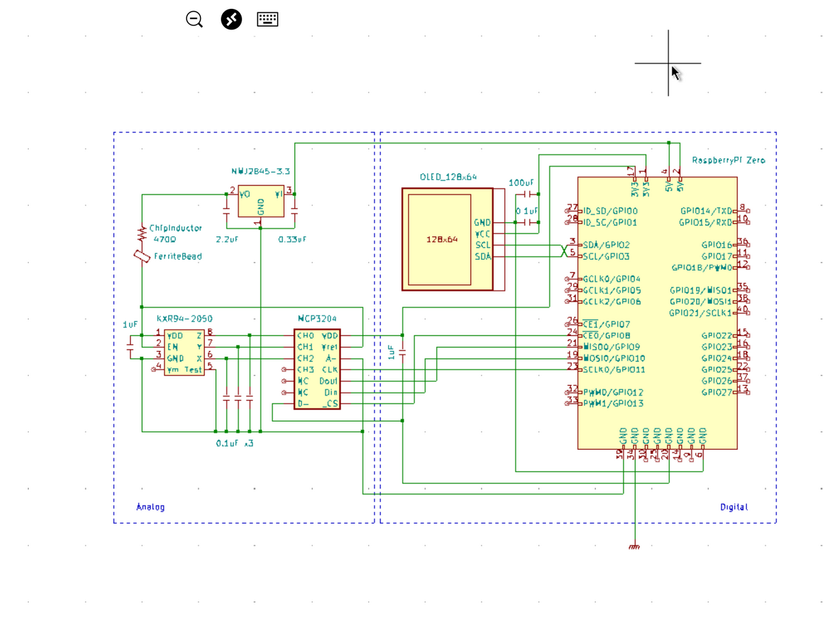
やったことの基本はアナログ部とデジタル部の分離。
1. デジタル部のVCC,GNDは I2C,SPIそれぞれの信号線付近のラズパイ 3.3V,GNDに接続してアナログ回路と分離
2. アナログ部のVCCとADCの基準電圧は3.3Vレギュレータの出力を使用
3. アナログ部のGNDは1で接続した以外のラズパイGNDへ接続
4. アナログ部のVCCの消費電流は数百μAオーダーなので少し大きめのインダクタ(+フェライトビーズ)を入れてノイズカット。
5. パスコンをメーカーが推奨する値のものに変更
6. ラズパイの鉄板シャーシをGNDに落としラズパイの輻射電波を遮断
あたりをやっていきます。アナログ部の消費電流が極端に少なくなるので、もはや3端子レギュレータではなくシャントレギュレータの方がいいのかもしれません。ハンディオシロで見たところ現状の3.3Vラインには最大160mVものリプルがのっており、12Bit・Vref=3.3VのADCにしてみれば200カウント、5%近くの変動になります。震度がなかなか下がらないわけです。上記対策を取ってどれくらいリプルが下がるのか挑戦です。
・配線の仕直し
現状の震度計の配線状況はこんな感じ。

これを引き直した回路図に基づいて配線し直していきます。
最初に一番のノイズ発生源であろうOLED周りの電源、パスコンを修正。


ハンダ面に被覆線で配線をすると後々何かと困るので極力被覆線を使わずに配線していきます。
パスコンをメーカー推奨値に交換し、アナログ部のVDDに秋月電子で買ったマイクロインダクタを入れたところで

一旦ノイズ対策の効果を確認してみます。
・無振動時の震度比較
記録を終了する震度を0にして震度を記録し続けた時のグラフをノイズ対策前後で比較してみます。
・ノイズ対策前

揺れがおさまっても震度 0.2あたりをフラフラしています。最低震度は0.056。
・OLEDをアナログから切り離した段階

震度0.1を切る回数がかなり増えてきました。ただ全体的にはまだ0.2あたりをフラついています。まだまだ対策が必要なようです。
・パスコンをメーカー指定値に交換
・アナログ部の電源にマイクロインダクタを挿入 したところ

お〜、なんとすごい!こりゃ効果てきめんです。
グラフの意味が分かりにくいかもしれませんが、震度計をつついてゆらしたあと

震度が完全にゼロになってくれるので測定が終了しグラフが途切れるのです。再びつついてゆらすとグラフは前回終了時の測点とつないでしまうため斜め線のグラフになってしまいますが、いつまでも震度がフラフラして測定が終了しないという事が全くなくなってしまいました。こいつはラッキー。
ゆれがおさまるとすぐに最大震度を報告してきます。

こりゃこれ以上対策とらなくても大丈夫かもしれません。
記録開始震度 0.5、記録終了震度0.0でゆすってみました。

キチンと震度0.5以上で記録を開始し震度0まで下がって記録を終了しています。開始震度が 0.5だと側を歩いただけで記録が始まるため震度計として現実的な値ではないのですが、ソフト・ハードのバグ取りのため当面いそがしく働いてもらうことにしときます。
◯やってみて
思いの外簡単にノイズの除去ができました。一安心。
まだ取っていない対策はADCのデジタル部分の電源分離とシャーシアース。シャーシアースは逆に少々おっかないところもあるのでとりあえずこの状態で様子を見てみることにします。既存の震度計の側において震度の更正(比較?)をやっていこうと考えてます。
◯おまけ
初の地震観測!

まだよくゆれる棚の上に置いているので記録した震度は3(2.52)。それらしい波形が記録されています。
ちなみに気象庁発表の震度は0(なし)、既存稼働中の震度計も起動せず、でした。
◯やってみて2
その後既存震度計の側にセットし震度の比較を始めたのですが

ブレッドボード配線はやはりノイズに弱いのでしょうか、既存震度計が新型震度計のノイズを拾って常に地震がある状態になってしまいました。

運よく震度が下がった時にしょっちゅう「家での震度は2です」と報告しまくってます。当然記録ファイルも毎分のように増加。
動作しているpythonのバージョンが低くて「f””」形式のフォーマット命令も使えない事ですし、そろそろ引退の時期なのかもしれません。
◯おまけ2
震度を100ms毎に記録していた制限を解除し、xyzの測定値も追加記録して全力で測定してみました。

おおむね5ms毎の記録になっているようです。
試しにこれをグラフ化してみたところ

・揺れと震度を同一表示

・揺れをXYZに分けて表示

・揺れのスケールを拡大

それらしい揺れのグラフが得られました。5ms毎の測定が実態に則しているのかはいかんせん素人なのでわからないのですが、震度と揺れの関係性がわかっておもしろいですね。


ラズパイで地震計(震度計)を作る (1)まずは製作
◯やりたいこと
3軸加速度センサー(KXR94-2050)、ADC(MCP3204)、OLED(SSD1306)で構成した震度計をHATとして製作し、ラズパイゼロに搭載して携帯型地震計(震度計)を製作する。

◯やった事
現在ブレッドボード上で動作している我が家の震度計、

地震が来るといち早く「家での震度は◯です」と教えてくれ次に何をするかの判断材料にとても役立っています。
震度計の元ネタは「たくや」さん。(感謝)
この記事を元に震度計を作ってここ何年か動かしていたのですが、動作中のOSが少々古くなってきており pythonのバージョンも3.5。そのため最近の3.9で作成したプログラムが動作しないという問題点が浮上してきました。そこでOSを新規インストールして新型に一新する事に。同時に測定回路をHAT化して携帯性をよくし、OLEDもつけて視覚からも情報を得られるようにグレードアップします。
・回路図
回路図は以下の通り。たくやさんの記事にi2c接続のOLED(SSD1306)を追加しています。

3軸センサーKXR94から出力されたx,y,zのアナログ値をMCP3204でAD変換し、SPI接続されたラズパイで読み取るというものです。
回路自体は特に面倒な点はないのですが、製作にあたって特に注意すべき点がノイズ対策。現に上記回路ではノイズの影響で震度が0.5以下になかなか下がらず一度地震が来ると永遠に揺れ続けるという問題が発生しました。これに関しては後半に詳しく対策を記載しときます。
・製作
まずは部品集め。ラズパイゼロと放熱兼用の鉄板ケースは手元にあるものを使い、残りはほぼ秋月電子で調達。

HAT用のユニバーサルボードはマルツで購入しました。

全体の部品配置はこんな感じで進めていきます。

途中OLEDの下に入るレギュレータとの取り合いをチェックしたり、

ラズパイとの取り合いもチェックしながら


組立て完了。

さっそく走らせてみます。

震度を求める計算式もたくやさんが公開されているものを使わせていただいています。
改めて感謝。ありがとうございます。
ちなみに地震がない時は時計を表示させていました。
・測定
さっそく震度計を揺らして震度を測定してみます。震度の記録は記録開始を震度1、記録終了を0.5のヒステリシスを待たせたシュミットトリガー方式でRAMディスク上に記録しており、地震終了後SDカード上に転送して保存しています。記録頻度は 100ms毎です。

卓上を滑らせた記録をグラフ化してみると

ガチャガチャ。
ユサユサで

デコボコ。
どうやらちゃんと動いているようです。
ちなみに過去におきた実際の地震の震度記録を見てみると

これは震源地がちょっと近目な震度3.4の記録で、初期微動でピークを打った後2秒で本震が来ています。
海洋性の地震だと終了までのすそのが長くなるようで、これなんかもろ海洋性地震。

初期微動ピークから本震ピークまで10秒以上、本震ピーク3.5を記録後ユサユサ、ユサユサとものすごく長く揺れています。近くの海の地下で地震が起きたようです。
・問題発生
先に述べたようにセンサーやADCがノイズを結構拾っているようで震度「0」にはなかなかなりません。原因として
1. ラズパイからのノイズ
2. アナログ回路とデジタル回路(OLED)の電源を共有しているため
3. パスコンの不適性配置
4. Vref(基準電圧)がVDDと直結
などが考えられます。次回(2)で対策を取っていきたいと思います。
マメタンに固形アルコール燃料で簡単着火(火起こし)
火の付きにくい豆タンにアルコールジェル系の固形燃料で簡単に火をつける方法。
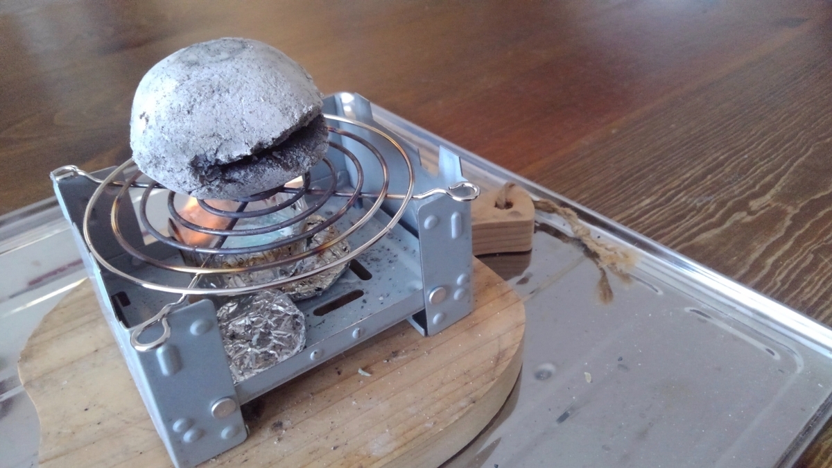
やり方は簡単、写真の通り。

アマゾンで売っていたアミ付きポケットストーブを断熱用の鍋敷きの上に置き、簡単に移動できるようステンレス製のお盆にのせます。

15gサイズの固形アルコール燃料を

2段重ねにして30gにしたものをセットし

マメタンをのせ火をつければ20分で火がつきます。

この時火とマメタンが十分近くにある事がコツなようです。
片面をじっくり15分ほど焼けば真っ白に焼き上がりますので残り5分でもう一面を焼きます。

マメタンが十分高温になっているので2面目はすぐに火が付き早々と真っ白になってくれます。

ノーマルマメタンはマッチ一本で着くスーパーマメタンと違い火の持ちがよく、スーパーマメタンの12〜16時間に対し24〜28時間と2晩布団の中を暖めてくれます。値段が安上がりな上に火の持ちがいいのでダブルでお得です。
ちなみにマメタンアンカを早く暖めたい場合は固形燃料をもう一個使って追加焼きすれば火の入り方が深くなり早く熱くなります。
・ガスと風
マメタンは着火時に有毒ガスを出すので外部の換気の良い場所で火をつけるのは鉄則です。ただ固形燃料は風に弱いためそのままだと火が風に流されうまく着火できません。ついたて等しっかりと防風対策が必要になります。燃料を2段重ねにするのは火力を強くして風に対抗するためです。防風対策がしっかりとれるのであれば、燃料の下に下駄を履かせ火をマメタンに近づければ一つでも火がつきます。片面一個づつ、二個で両面焼きが可能です。私はこの方式でやってます。
・おまけ
ノーマルマメタンの灰はスーパーマメタンに比べると柔らかくすぐに割れてしまいます。というか、スーパーマメタンの灰が固いんでしょうか。写真は着火から24時間たった豆炭。
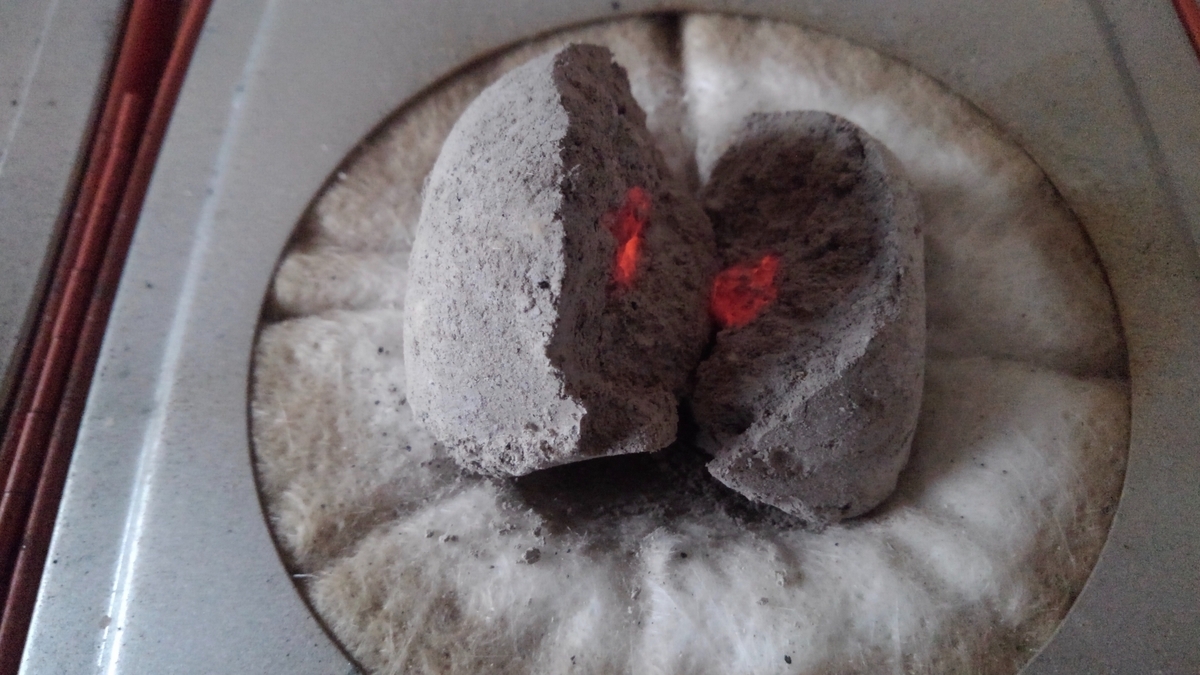
灰がやわらかいので火鉢に移そうとした時に割れてしまいました。まだ火が残っていてアンカ自体も相当熱い状態です。
・おまけ2
豆タンは普段車庫に保管してあるのですが、普段使い用に火消しツボにいくつか入れて部屋に置いています。冬で乾燥が進むせいかパックマンモード、アッカンベー豆タンが発生します。
特に問題はないとは思うんですが…。
(写真はすっかり火がついたので家の中に持ってきた時の豆タンです。)
ラズパイでメッシュWiFiネットワークを構築する(4) NODEの準備
◯やりたいこと
(1)〜(3)で構築されたメッシュネットワークへ NODEを追加する。
◯やったこと
5. その他 NODEの作成
(2)と(3)で最低限のメッシュネットワークが構築できたので、メッシュネットにその他のノードを追加していきます。ノードはメッシュデバイスとしてパケットのリレーを担当しながら、センサーなどを装備してデータの発信や受信を行う事もできます。メッシュに参加するには wlan0一つがあればいいのでラズパイゼロで充分に活躍できます。
5-1. ラズパイの準備
ここではラズパイZeroへインストールする例で進めていきます。Zeroは(1)の要領で新規に準備したものでもいいですし、センサー搭載など既に何かが動作しているものでも構いません。既存動作中のZeroにいくつかインストールしてみましたが特に問題なく動いてくれています。
ホームネット側から wlan0に接続しターミナルソフトから sshで Zeroにログインしておきます。
5-2. batctl ツールのインストール
ゲートウェイの設定 3-2と同じ処理です。batctlの設定ファイルの内容が一般ノード用に変更になります。
sudo apt-get install -y batctl
nano ~/start-batman-adv.sh
・ファイル内容
#!/bin/bash
# batman-adv interface to use
sudo batctl if add wlan0
sudo ifconfig bat0 mtu 1468

# Tell batman-adv this is a gateway client
sudo batctl gw_mode client

# Activates batman-adv interfaces
sudo ifconfig wlan0 up
sudo ifconfig bat0 up
忘れずにスクリプトを実行可能な状態にしておきます。
chmod +x ~/start-batman-adv.sh
5-3. wlan0のネットワーク定義の設定
ゲートウェイ設定 3-3と全く同じ内容でファイル設定をします。
sudo nano /etc/network/interfaces.d/wlan0
・ファイル内容
auto wlan0
iface wlan0 inet manual
wireless-channel 1
wireless-essid call-code-mesh
wireless-mode ad-hoc
wireless-key 1234567890
5-4. batman-advモジュールのロード
echo 'batman-adv' | sudo tee --append /etc/modules
5-5. wlan0をDHCPプロセスの管理から外す
wlan0を DHPCの管理下から除外します。
echo 'denyinterfaces wlan0' | sudo tee --append /etc/dhcpcd.conf
5-6. 起動時実行スクリプトの定義
ここもゲートウェイ設定 3-6と同様の設定を行います。
sudo nano /etc/rc.local
ファイル内の exit 0 の前に
/home/pi/start-batman-adv.sh &
の1行を挿入しておきます。
5-7. ノードへのログイン
以上でノードの設定は終了です。ここで再起動しますが、再起動するとノードはメッシュネット上に移動しますのでホームネット側からのアクセスができなくなります。ブリッジで行ったようにゲートウェイを経由して sshの2段接続でログインします。
ちなみにゲートウェイにログインした時点で以下のコマンドを実行するとメッシュネット上で pingに反応してくれる IPアドレスの一覧を表示してくれます。
echo 192.168.199.{1..254} | xargs -P256 -n1 ping -s1 -c1 -W1 | grep ttl
「なんかいろいろ」さんより(https://orebibou.com/ja/home/201505/20150518_001/)
5-8. インターフェースの動作状況確認
ゲートウェイやブリッジで行ったように以下のコマンドで動作の確認ができます。
ifconfig
iwconfig
sudo batctl if
sudo batctl n
インターネットへの接続確認は
ping www.ibm.com -c 5
でルーティングとバックが正しく行われているかがわかります。
〜 続く 〜

ラズパイでメッシュWiFiネットワークを構築する(3) Bridge NODEの準備
◯やりたいこと
(2)で準備したゲートウェイに引き続き、(1)の要領で準備した2台目のラズパイへメッシュネット上で動作するブリッジノードをインストールします。
◯やったこと
4. Bridge NODE(BR)の作成
ここで準備するブリッジノードは wlan0側がメッシュネット上に接続されているNODEの一つで eth0側に接続される非メッシュデバイスとのパケット中継を担当します。wlan0・eth0どちら側も見た目は同じメッシュネットワーク上にあるように見えます。ブリッジを家の隅っこに持っていったとしてもあちこちの NODEがバケツリレーでパケットを転送してくれるので、eth0と PCを LANケーブルで接続するとPCは普通にメッシュネット上にあるように動作します。IPアドレスもメッシュ上のDHCPサーバー(ゲートウェイ)からキチンと 192.168.199.xxxのアドレスを取得します。当然メッシュネット上にある各NODEとのやりとりも普通にできます。WiFiドングルを追加すれば eth0の代わりに WiFiでの機器接続も可能になります。

4-1. ラズパイの準備
ラズパイ 4B+が入手困難なのでゲートウェイと同じく在庫品の 3B+を引っ張り出してきてブリッジを構成します。ブリッジノードは設定が終わって再起動するとホームネット側からは見る事ができなくなりますので気合を入れて一発動作を狙っていきます。まあ最悪 eth0に PCを接続し直せばホームネット上で操作したのと同様な操作をする事は可能なのですが、iPadからリモートでWindowsにログインしている私の環境では非常に手間がかかる処理になりますのでできればやらずに済ませたいところです。
(1)の要領でセットアップしたラズパイは順調に起動すれば wlan0がホーム側ネットに接続して起動しますので、ターミナルソフトから sshでログインしておきます。
4-2. batctl ツールのインストール
ゲートウェイの設定 3-2と同じ処理です。batctlの設定ファイルの内容がブリッジ用に変更になります。
sudo apt-get install -y batctl
nano ~/start-batman-adv.sh
・ファイル内容
#!/bin/bash
# batman-adv interface to use
sudo batctl if add wlan0
sudo ifconfig bat0 mtu 1468

sudo brctl addbr br0
sudo brctl addif br0 eth0 bat0

# Tell batman-adv this is a gateway client
sudo batctl gw_mode client

# Activates batman-adv interfaces
sudo ifconfig wlan0 up
sudo ifconfig bat0 up

# Restart DHCP now bridge and mesh network are up
sudo dhclient -r br0
sudo dhclient br0
ちなみにブリッジノードの IPアドレスを固定化したい場合は最下行2行の代わりに
sudo ifconfig br0 192.168.199.xxx
としておけば固定IPで起動します。
ここでも忘れずにスクリプトを実行可能な状態にしておきます。
chmod +x ~/start-batman-adv.sh
4-3. wlan0のネットワーク定義の設定
ゲートウェイ設定 3-3と全く同じ内容でファイル設定をします。
sudo nano /etc/network/interfaces.d/wlan0
・ファイル内容
auto wlan0
iface wlan0 inet manual
wireless-channel 1
wireless-essid call-code-mesh
wireless-mode ad-hoc
wireless-key 1234567890
4-4. batman-advモジュールのロード
echo 'batman-adv' | sudo tee --append /etc/modules
4-5. wlan0,eth0,bat0をDHCPプロセスの管理から外す
ブリッジノードではwlan0に加え eth0, bat0もDHPCの管理下から除外します。
echo 'denyinterfaces wlan0 eth0 bat0' | sudo tee --append /etc/dhcpcd.conf
4-6. 起動時実行スクリプトの定義
ここもゲートウェイ設定 3-6と同様の設定を行います。
sudo nano /etc/rc.local
ファイル内の exit 0 の前に
/home/pi/start-batman-adv.sh &
の1行を挿入しておきます。
4-7. ブリッジユーティリティのインストール
ここからはブリッジノード専用のインストールになります。まずはブリッジユーティリティのインストールから行います。
sudo apt-get install -y bridge-utils
4-8. eth0の設定
wlan0側(メッシュ側)でリレーしてきたパケットを橋渡し(ブリッジ)する eth0の設定を行います。この設定を行うとイーサネットポートをホットプラグ(自由に抜き差し)できるようになります。設定ファイルに以下の内容を定義します。
sudo nano /etc/network/interfaces.d/eth0
・ファイル内容
auto eth0
allow-hotplug eth0
iface eth0 inet manual
4-9. ブリッジノードへのログイン
以上で設定が完了しましたので再起動します。再起動するとブリッジはメッシュネット上に移動してしまいますのでホームネット側から直接操作することができなくなります。ブリッジへWindowsマシンを直接 LAN接続できる場合は直接操作が可能なのですが、ここではゲートウェイにホームネット側から sshで一度ログインしさらにゲートウェイ上からメッシュネット側のブリッジに sshでログインする方法を取ります。要は sshの2段接続です。
ホームネット側からゲートウェイにログインし、
ssh pi@192.168.1.xxx
DHCPサーバーのアドレスリース記録を見てブリッジの IPアドレスを確認します。
cat /var/lib/misc/dnsmasq.leases
そのアドレスに sshでログインします。
ssh pi@192.168.199.xxx
4-10. インターフェースの動作状況確認
ブリッジにログインできたら最初にインターフェースの動作状況を確認します。
ifconfig
次のように表示されれば正常に動作しています。
bat0: flags=4163<UP,BROADCAST,RUNNING,MULTICAST>  mtu 1468
            inet6 fe80::e838:85ff:fe06:8265  prefixlen 64  scopeid 0x20<link>
            ether ea:38:85:06:82:65  txqueuelen 1000  (Ethernet)
            RX packets 16589  bytes 9220389 (8.7 MiB)
            RX errors 0  dropped 0  overruns 0  frame 0
            TX packets 14460  bytes 1905164 (1.8 MiB)
            TX errors 0  dropped 19 overruns 0  carrier 0  collisions 0

    br0: flags=4163<UP,BROADCAST,RUNNING,MULTICAST>  mtu 1468
            inet 192.168.199.34  netmask 255.255.255.0  broadcast 192.168.199.255
            inet6 fe80::4e41:fc4e:b18c:ffd0  prefixlen 64  scopeid 0x20<link>
            ether b8:27:eb:e8:18:b0  txqueuelen 1000  (Ethernet)
            RX packets 3261  bytes 213663 (208.6 KiB)
            RX errors 0  dropped 0  overruns 0  frame 0
            TX packets 1053  bytes 208548 (203.6 KiB)
            TX errors 0  dropped 0 overruns 0  carrier 0  collisions 0

    eth0: flags=4163<UP,BROADCAST,RUNNING,MULTICAST>  mtu 1500
            inet6 fe80::ba27:ebff:fee8:18b0  prefixlen 64  scopeid 0x20<link>
            ether b8:27:eb:e8:18:b0  txqueuelen 1000  (Ethernet)
            RX packets 15714  bytes 2010018 (1.9 MiB)
            RX errors 0  dropped 0  overruns 0  frame 0
            TX packets 16090  bytes 9413607 (8.9 MiB)
            TX errors 0  dropped 0 overruns 0  carrier 0  collisions 0

    lo: flags=73<UP,LOOPBACK,RUNNING>  mtu 65536
            inet 127.0.0.1  netmask 255.0.0.0
            inet6 ::1  prefixlen 128  scopeid 0x10<host>
            loop  txqueuelen 1000  (Local Loopback)
            RX packets 3  bytes 360 (360.0 B)
            RX errors 0  dropped 0  overruns 0  frame 0
            TX packets 3  bytes 360 (360.0 B)
            TX errors 0  dropped 0 overruns 0  carrier 0  collisions 0

    wlan0: flags=4163<UP,BROADCAST,RUNNING,MULTICAST>  mtu 1500
            inet6 fe80::ba27:ebff:febd:4de5  prefixlen 64  scopeid 0x20<link>
            ether b8:27:eb:bd:4d:e5  txqueuelen 1000  (Ethernet)
            RX packets 65722  bytes 11991421 (11.4 MiB)
            RX errors 0  dropped 0  overruns 0  frame 0
            TX packets 39946  bytes 4886290 (4.6 MiB)
            TX errors 0  dropped 0 overruns 0  carrier 0  collisions 0
チェック点
・br0にメッシュネットワーク内の IPアドレスが割り振られている
・bat0,eth0,wlan0には IPアドレスが割り振られていない
続いてブリッジインターフェースの詳細を表示して
sudo brctl show
bat0と eth0がブリッジしている事を確認します。
bridge name bridge id       STP enabled interfaces
br0     8000.b827ebe818b0   no      bat0
                                    eth0
ブリッジのインターフェースがメッシュネットワークに参加できているかを確認するには
sudo batctl if
wlan0: active
でwlan0がメッシュに参加している事がわかりますし、
sudo batctl n
で自分から見える近くのメッシュノードが表示されます。
[B.A.T.M.A.N. adv 2021.3, MainIF/MAC: wlan0/b8:27:eb:04:3e:57 (bat0/ba:d1:69:83:e4:2f BATMAN_IV)]
IF             Neighbor              last-seen
        wlan0     b8:27:eb:33:d4:ad    0.920s
〜 続く 〜