◯やりたいこと
(1)で製作した電流計付き電源のスケッチを作成する。
◯やったこと
シャント抵抗の電圧をAD変換し電流値に変換してOLEDに次のように表示します。

スケッチは以下の通り。
/*
*
*    MCP3245(16Bit ADC)電流計 WR02_ADC_OLED v0.0.4b
*
*/
// Standerd Library (IDE v1.8.19)
#include              <Arduino.h>
#include              <Wire.h>

// Board Library
/* ESP8266 Boards(v2.7.2)/Generic ESP8266 Module */
#include              <WiFiClient.h>        // wifi_set_sleep_type()

// Install Library
/* OLED */
#include              <Adafruit_SSD1306.h>  // v2.5.7

// Global Value
/* UART */
#define TX            1         // D1
#define RX            3         // D3

/* I2C */
#define I2C_SDA       2         // D2
#define I2C_SCK       0         // D0
#define I2C_CLK       100000    // fSCL=100KHz

/* OLED */
#define OLED_ADR      0x3C      // I2C Address
#define SCREEN_WIDTH  128       // OLED display width, in pixels
#define SCREEN_HEIGHT 64        // OLED display height, in pixels
#define OLED_RESET    -1        // Reset pin # (or -1 if sharing Arduino reset pin)
Adafruit_SSD1306      display(SCREEN_WIDTH, SCREEN_HEIGHT, &Wire, OLED_RESET);
unsigned long dsptime = 0;

/* ADC */
#define ADC_ADR       0x68      // I2C Address
#define ADC_REF       2.048     // [V]:Voltage Reference
#define SHUNT         0.1       // [Ω]:Shunt Resistor
float curr_max =      0;
float curr_min =      9999.9;

void setup() {
  // ハードウエア 初期設定
  /* Sleep Mode */
  wifi_set_sleep_type(MODEM_SLEEP_T);
  Serial.end();

  /* I2C */
  Wire.begin   (I2C_SDA, I2C_SCK);
  Wire.setClock(I2C_CLK);

  /* OLED(SSD1306) */
  display.begin(SSD1306_SWITCHCAPVCC, OLED_ADR);
  //display.begin();

  /* OLED画面初期表示 */
  display.clearDisplay();
  display.setTextColor(WHITE);
  display.setTextSize(2);
  display.setCursor(  0,  0);
  display.println("SSD1306");
  display.setTextSize(1);
  display.setCursor(  0, 19);
  display.println("OLED Start.");
  display.display();
  delay(1000);
}

//
void loop() {
  // 初期設定
  char  buf1[9],  buf2[21];
  float shnt=0.0, curr=0.0;

  // ADC 設定 コマンド送信 (Configuration Register)
  /*   Bit  7: _RDY
  /*   Bit6,5: channel
  /*   Bit  4: 1=連続 0=ワンショット測定
  /*   Bit3,2: 00=12Bit 01=14Bit 10=16Bit 11=--
  /*   Bit1,0: 00=x1    01=x2    10=x4    11=x8 */
  Wire.beginTransmission(ADC_ADR);
  Wire.write(0b10001001);
  Wire.endTransmission();

  // データ確定待ち(16Bit:15SPS=67ms)
  delay(100);

  // ADC data,config 受信(1sec以内)
  unsigned long timeout = millis();
  while(millis() - timeout < 1000) {
    // データ(3Byte)要求
    Wire.requestFrom(ADC_ADR, 3);

    // 3Byte未確定は 10mS待機を 3回だけ実施
    byte  conf=0x80;
    for (uint8_t j=0; j<3; j++) {
      if(Wire.available() >= 3) {
        // ADC i2cデータ -> 数値変換
        shnt =(Wire.read()<< 8)+ Wire.read();
        conf = Wire.read();
        break;
      }
      delay(10);
    }
    // 受信データ確定(Bit7=0)で測定終了
    if (conf<0x80) break;
    delay(10);
  }

  // 電圧->電流値変換 基準電圧:ADC_REF shunt抵抗値:SHUNT
  /*   ADC:12Bit 1mV   240SPS (-2048~2047)
  /*       14Bit 250uV  60SPS (-8192~8191)
  /*       16Bit 62.5uV 15SPS (-32768~32767) */
  shnt = shnt/32767;      // 測定精度 16Bit
  shnt*= ADC_REF/2;       // 測定倍率 2倍(max1.024A)
  shnt*= 1000;            // 表示単位 mA
  if (shnt>2047) shnt=0;  // 2047を超えた値はerr
  curr = shnt*(1/SHUNT);  // シャント抵抗倍率

  // max,min計算
  if (curr_max<curr)            curr_max=curr;
  if (curr_min>curr && curr!=0) curr_min=curr;

  // 表示
  if ((millis()-dsptime)>=100) {
    display.clearDisplay();
    display.setTextColor(WHITE);

    /* Current */
    display.drawRect(0, 0, 127, 18, WHITE);
    display.setTextSize(2);
    display.setCursor(  2, 2);
    dtostrf(curr,8,2,buf1);
    sprintf(buf2, "%s", buf1);
    display.print(buf2);
    display.setCursor(102, 2);
    display.println("mA");

    /* Bus-V */
    display.setTextSize(1);
    display.setCursor( 12, 22);
    display.println("Bus-V :    3.30  V");
    /* Shunt-V */
    display.setCursor( 12, 30);
    dtostrf(shnt,8,2,buf1);
    sprintf(buf2, "ShuntV:%s mV", buf1);
    display.println(buf2);
    /* Power */
    display.setCursor( 12, 38);
    dtostrf((curr*3.3),8,2,buf1);
    sprintf(buf2, "Power :%s mW", buf1);
    display.println(buf2);

    /* max current */
    display.setCursor( 12, 48);
    dtostrf(curr_max,8,2,buf1);
    sprintf(buf2, "max   :%s mA", buf1);
    display.println(buf2);
    /* min current */
    display.setCursor( 12, 56);
    dtostrf(curr_min,8,2,buf1);
    sprintf(buf2, "min   :%s mA", buf1);
    display.println(buf2);

    display.display();
    dsptime = millis();
  }
}
こまめにコメントを記入していますのでプログラムの流れは大体はつかめると思います。ADCとデータをやり取りする部分には無限ループしないよう3つほど制限をかけており、
1. ADCから読込んだconfigデータのBit7(RDYフラグ)が0になった(=確定値を受信)
2. ADCからの返信データ(3byte)未着待ちは1回10msを3回まで
3. 測定時間は最大1sec
でループから抜け出てきます。
◯やってみて
写真のハードウエアは(1)からちょっとグレードアップしていて、電源供給用に専用のレギュレータが追加されています。そのため少々安心して大きめの電流を流す事が出来ています。
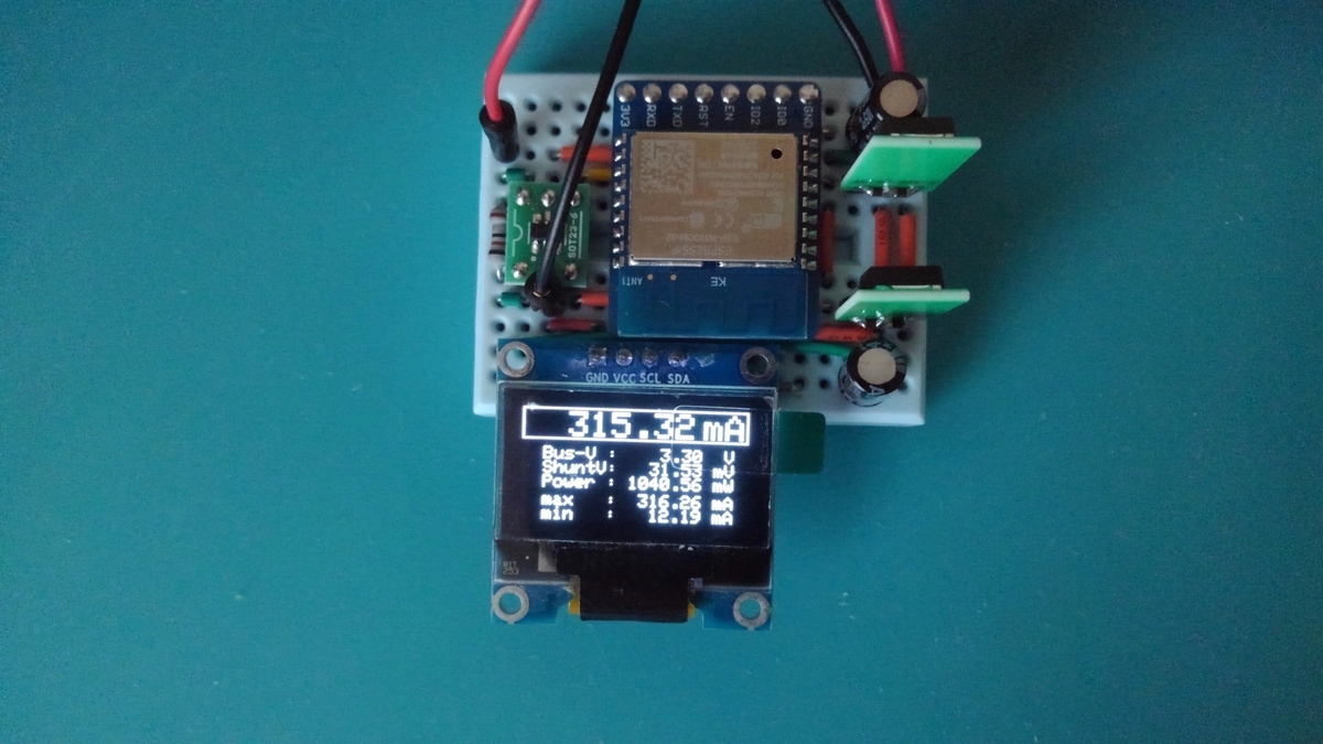
とはいえレギュレータはかなり熱くなりますので、本番の実機では放熱対策を取ろうと考えてます。